Computer Aided Design is the name given to a software package that lets the designer accomplish the following functions: sketch a two-dimensional (2D) sketch, create a three-dimensional body from the two-dimensional sketch, assemble multiple three-dimensional (3D) bodies into an assembly, and create an engineering drawing of the three-dimensional body. These packages typically also come with some analysis packages for structural failure and fluid flow analysis. Out of the multitude of packages available in the market, this book has chosen to focus on Autodesk Fusion 360.
![]()
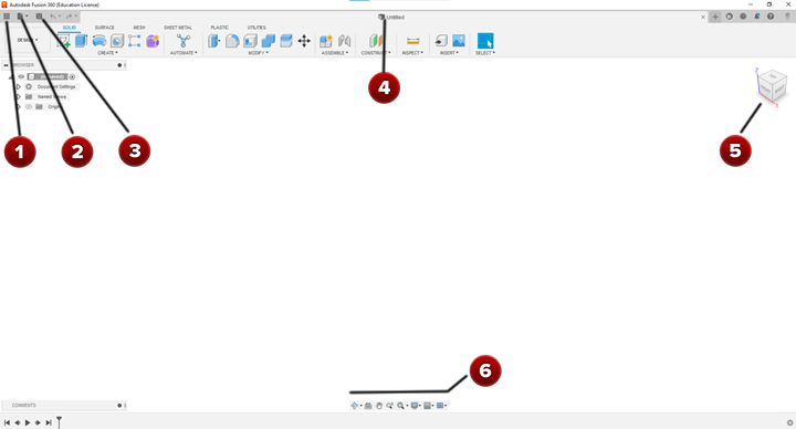
The user interface of the Autodesk Fusion 360 is shown in Figure \(\PageIndex<2>\) below.
The Bento menu is labeled number one (1) in Figure \(\PageIndex<2>\) above. By clicking on this menu, the recent files saved on the Fusion 360 cloud can be accessed. A detailed version of the Bento menu is shown in Figure \(\PageIndex\).  After clicking on the Bento menu button, a sidebar opens up on the left side of the interface. This sidebar contains an icon of the saved file with the saved name and date last modified. Figure \(\PageIndex\) shows this sidebar in more detail.
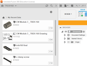
There is a file drop down menu that is labeled as number two (2) in Figure \(\PageIndex<2>\) above. A detailed version of the file dropdown menu is shown in Figure \(\PageIndex\) and the menu that this button brings up is shown in Figure \(\PageIndex\). 
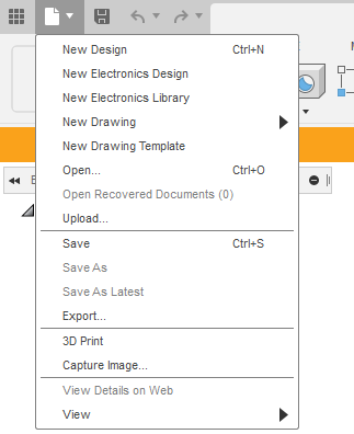 Within the options in the file drop down menu, the user can create a new design, which refers to a 2D sketch or 3D model. The electronics design will let you create and simulate an electronic circuit that. The new drawing will allow for an engineering drawing to be created. This drawing has to be based on a 3D model that has already been created. The option Open allows for opening of a preexisting file. The Upload option is used to move a file saved on the computer the user’s cloud based account with Autodesk. The Save option is used to save a file that the user is currently working on. For a 3D model, the file format is (*.f3d). If the file has never been saved before, it will be saved as a new file and if the file has been saved before, it will let the user overwrite the file. Export allows for a currently open file to be saved in a different file format that the standard Autodesk file format, such as STEP or IGES. This allows the file to be read by software packages other than the one on which the file was created. The 3D Print option prepares the current 3D model to be printed out using a 3D printer. The Capture Image option allows for capturing the current model on the screen and saving it as an image file.

The Floppy Disk shaped button allows the user to save the current project. It is shown in Figure \(\PageIndex<7>\). The floppy disk icon is labeled number three (3) in Figure \(\PageIndex\) above.
The name of the file is displayed at the top of the tab and is labeled as number four (4) in Figure \(\PageIndex<2>\).
The Coordinate System is labeled as number five (5) in Figure \(\PageIndex<2>\). This coordinate system is used to indicate the plane in which the user is viewing the projection.
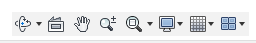
Within the CAD environment, there are ways to manipulate the current model in 3D space. The toolbar labeled number six (6) in Figure (\PageIndex<2>\) is located at the bottom of the interface and allows the user to manipulate the models. These are shown in more detail in Figure \(\PageIndex\).
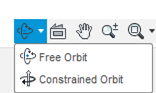
The Orbit button, shown in Figure \(\PageIndex<9>\), allows for two types of manipulation: free and constrained. In order to use either of these options the user has to hold down the shift button, middle button of the mouse and move the mouse around. Free orbit allows the model to be moved anywhere in 3D space and in any direction but the constrained option only allows the model to be moved around a fixed point in space.

The View button brings the selected component in an assembly to the front. See Figure \(\PageIndex<10>\).

The Pan button allows the model to be moved around in 3D space without changing the orientation of the model. See Figure \(\PageIndex<11>\).

The Zoom In/Out and Fit option allows the user to adjust the display proportion of the selected model. See Figure \(\PageIndex<12>\).
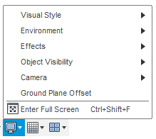
The Display settings options allow for the model to be viewed in different backgrounds, camera angles, and lighting options. See Figure \(\PageIndex<13>\).
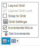
The Grids and Snaps options allow for essentially a graph paper functionality while sketching. See Figure \(\PageIndex<14>\).

The Viewports option allows for multiple views to be displayed simultaneously on the current screen. See Figure \(\PageIndex<15>\).